Seafloor Swathe Survey for Search and Rescue Mission of Air Asia
QZ8501
POERBANDONO, Indonesia
1) On the 28 December, 2014, a commercial
airplane, Air Asia QZ8501 flying from Surabaya (Indonesia) to Singapore,
was reported missing and believed to crash into the sea. This paper
focuses upon the search for the flight. Three survey zones were covered:
Area-1 (the position of last contact from the airplane), Area-2 (where
debris and bodies from the crashed airplane were recovered), and Area-3
(the last RADAR sighting). Area-2 is about 15 km SE of Area-1 and Area-3
is about 89 km NW of Area-2. The survey is executed as seabed search by
using Side Scan Sonar imagery and Multi Beam Echo Sounder point cloud
data.
Key words: Scouting procedure, SSS contact, MBES
height, ROV inspection
 This article in
.pdf-format (14 pages)
This article in
.pdf-format (14 pages)
SUMMARY
Search survey operation is launched by the Indonesian Association of
Marine Survey Contractors (AKSLI) between the December 31st, 2014 and
the January 16th, 2015. The operation deploys MGS GEOSURVEY vessel under
the command of the National Agency for Search and Rescue (BASARNAS). As
much as 16 technical crews were onboard. They serve as survey and
Remotely Operated Vehicle (ROV) teams led by a party chief. The
operation aims at searching the missing commercial plane, Air Asia
QZ8501, formally announced on the December 28th, 2014 over NW of Java
Sea, Indonesia. Three survey zones were covered: Area-1 (the position of
last contact from the airplane), Area-2 (where debris and bodies from
the crashed airplane were recovered), and Area-3 (the last RADAR
sighting). Area-2 is about 15 km SE of Area-1 and Area-3 is about 89 km
NW of Area-2.
The survey is executed as seabed search by using Side Scan Sonar
imagery and Multi Beam Echo Sounder point cloud data. The search relies
on detection of sonar contacts, continued by interpretation of manmade
or non-natural features identified as suspected objects. Suspected
objects are defined on the basis of anomalous dimension, particularly
height, with respect to the ambient. Subsequently, visual recognition
employing ROV and manual inspection (i.e. divers) supported by
underwater positioning system are done to verify whether or not the
object is part of the missing airplane. Out of three survey areas, 13
sonar contacts were detected and subsequently eight suspected objects
were identified and verified. This 17 days launch mission was able to
discover major parts of the crashed airplane in Area-3.
Three sites of the crashed airplane were located: the tail, seats and
corpses, and body and wings. They are situated on the seabed elongated
approximately NW-SE across roughly 3100 m distance, with the following
detail of horizontal positions:
- 03°37'50.05"S, 109°43'39.54"E for Seats and Corpses
- 03°38'39.26"S, 109°43'45.07"E for Tail
- 03°37'21.27"S, 109°42'42.52"E for Body and Wings
Seafloor Swathe Survey for Search and Rescue Mission of Air Asia
QZ8501
1. INTRODUCTION
On the 28th of December, 2014, a commercial airplane, Air Asia QZ8501
flying from Surabaya (Indonesia) to Singapore, was reported missing and
believed to crash into the sea. The latest known position is situated in
the very NW of Java Sea, Indonesia. In supporting national Search and
Rescue (SAR) mission, the Indonesian Association of Marine Survey
Contractors (AKSLI) launched a search survey operation with MGS
GEOSURVEY vessel. AKSLI team is mobilized on December 31st, 2014 from
Tanjung Priok Port, Jakarta and the entire operation is accomplished on
the 16th of January, 2015. The search survey operation is carried out
under the command of the Indonesian National Agency for Search and
Rescue (BASARNAS). In Figure 1, parties involved in the mission are
shown.
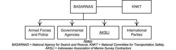
Figure 1 Order hierarchy of Search and Rescue (SAR) mission
This paper is prepared in order to document essential technical parts
of the search survey operation. The documentation will include primarily
the sequence of scouting procedure. The organization of personnel and
the deployment of equipments are also presented. It is expected that the
readership is able to assess how recent best practice of hydrographic
survey could be contributed to specific mission, i.e. underwater SAR.
The primary source of information presented in this paper is originated
from AKSLI survey report and daily field log (AKSLI, 2015). To the
extent of completeness of survey report and daily field log, this paper
is written in its best accuracy, in terms of procedure, personnel, and
equipments.
2. SURVEY OPERATION
2.1 Survey Plan
The purpose of the launching of search survey operation is to conduct
seafloor mapping in order to find the main body or parts of the missing
Air Asia QZ8501. The mapping is hence intended to discriminate manmade
objects (possibly leading to an interpretation of parts of the missing
plane) from natural seabed including inherent features surrounding them.
The search survey operation was initially done in Area-1. Area-1 is
known as the position of the latest contact from the airplane. The next
survey zone (Area-2) is where floating debris and bodies were recovered.
Later on, another zone (Area-3) situated several tens of kilometres NW
away from the first two zones was also surveyed. Area-3 is the recorded
latest RADAR sighting and lost contact. These locations are situated in
the N of Java Sea, SE of Belitung Island, Indonesia.
Figure 2 shows the three survey zones and their approximate distance.
Area-2 is about 15 km away SE of Area-1, while Area 3 is roughly 89 km
away NW of Area-2. The central coordinates of all survey areas are
supplied by BASARNAS command centre. AKSLI team decides the search
strategy by planning the survey extent (boundaries), survey line, and
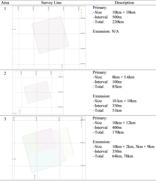
line interval. Area-1 is 10 km by 10 km in size and consists of 22
mainlines with 500 m spacing. Area-2 is 5 km by 5.6 km in size and
consists of 17 main lines with 350 m spacing. The survey corridor was
extended 3 km SW. Area-3, is 10 km by 12 km in size and consists of 18
main lines with 400 m of spacing. Here, the survey corridor was extended
4 km SW and 6 km SSE with equal spacing, and widen 2 km and 3 km NW with
350 m spacing. In Table 1, description of survey line is shown.
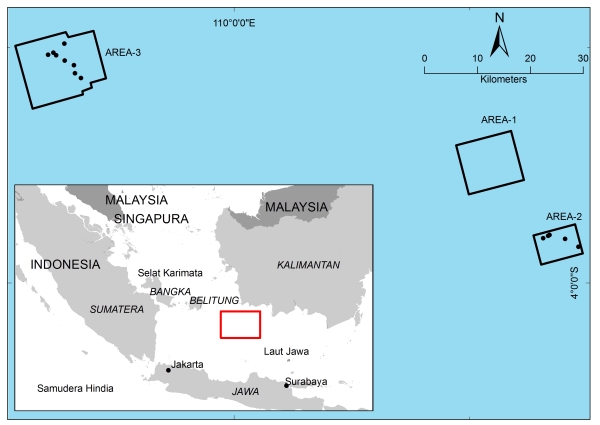
Figure 2 Search survey areas
Table 1 Volume (i.e. line, length) of each of survey areas on UTM49S
2.2 Procedure
In each of survey zone, the tracking of survey line is started from
the line intercepting the central coordinates, hereinafter termed as the
primary survey line. Line orientation is drawn out parallel to
approximate current direction. The progress of the tracking of survey
line is made by the sailing of survey vessel away line-by-line from the
primary survey line. Over the course of survey lines, the basic
procedure for search survey follows.
- Detection: The detection is intended to collect
sonar contact in the swept area. This is done by deployment of Side
Scan Sonar (SSS). Such a sonar contact is defined as higher acoustic
return (stronger reflectivity with respect to the ambient) observed
by SSS. Approximation of horizontal positions and dimension (i.e.
length, width, height) of all sonar contacts are done employing
Multi Beam Echo Sounder (MBES).
- Interpretation: All recorded sonar contacts
from SSS image subsequently undergo interpretation. The
interpretation is done by estimating the dimension of such a sonar
contact from MBES point cloud data. Suspected objects are defined on
the basis of anomalous dimension, particularly height, with respect
to the ambient. It is thought that anomalous height of sonar contact
leads to higher probability of manmade or non-natural features.
- Verification: The verification is aiming at
confirming whether or not a suspected object is actually the part of
the missing air plane. It is done basically by using visual
inspection employing deployment of ROV, and followed by manual
inspection by sending rescue divers. In order to precisely locate
the position of the object, the diver is equipped by underwater
positioning beacon.
Throughout the entire cycle of search survey procedure, the
processing of data, the subsequent interpretation, including charting
and reporting are carried out simultaneously along with the onboard data
acquisition. No water level correction due to tide is applied.
2.3 Equipments and Personnel
The survey work entails the deployment of dual head MBES, dual
frequency SSS, and the operation of ROV, including horizontal
positioning system using differential Global Navigation Satellite System
(GNSS). SSS is meant to detect bottom reflectivity, while MBES is
intended to approximate the apparent height. Among others, the primary
equipments and their peripherals are: GNSS heading, gyro compass, ultra
short base line (USBL) system, navigation system software, motion
reference unit, sound velocity sensor, and
Conductivity-Temperature-Depth (CTD) profiler.
Field calibrations and functional tests were undertaken. They are
applied to the primary and secondary positioning systems, gyro compass,
echo sounder transducer draft, as well as vessel and sensor offset.
Another tests were also done for online navigation computers, fix
annotation and interfacing from the navigation computer to the analogue
recording systems, and motion sensors. MBES, SSS, and CTD systems
experienced specific wet tests. On-site calibration and functional tests
were done for vertical acoustic velocity profile, rub test of SSS
pre-dive check, and for ROV.
Figure 3 shows the structure of organization of the technical team
on-board. A party chief leads two teams (i.e. survey, ROV) and manages
as much as 16 technical personnel. Survey team is composed by personnel
assigned as hydrographic surveyor, survey technician, geophysicist, and
MBES processor. The ROV team consists of ROV pilot and ROV technician.
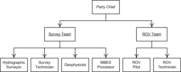
Figure 3 On-board assignments of technical crews
3. RESULTS
SSS data is presented as mosaics of grey shaded imagery. Its
brightness corresponds to the strength of the returning signal and is
used to infer bottom type (sediment texture and roughness) and to proxy
substrate characteristic. From this, it is seen that the seabed is
characterized by low to high sonar reflectivity. High sonar reflectivity
is interpreted as coarser and mobile sediments, while low sonar
reflectivity is indicative of softer sediment. Indication of mobile
sediments associated with presence of sand ridges was found in Area-3.
MBES data is presented as point cloud, from which the geometrical
appearance of seabed can be identified. It is known from here on that
the water depths within the survey areas vary between approximately 25 m
and 38 m. The seabed relief in the surveyed zones is considerably
undulated indicating bathymetrical irregularity, and slightly dipping to
NE at an approximate height of less than 0.5 m. Such an irregularity is
mostly associated with micro-sized ridges and depression of seabed.
Thirteen sonar contacts were detected from SSS imagery. They show
higher reflectivity with respect to the ambient. The majority of these
contacts indicate substantially apparent heights as approximated from
MBES point cloud data. Therefore, these contacts are believed to
represent man-made object. Details are elaborated as follow.
3.1 Area-1
No significant sonar contact is recorded here.
3.2 Area-2
As detected by SSS, five sonar contacts were recorded here (Figure 4)
and considered as suspected objects due to their size. Details of
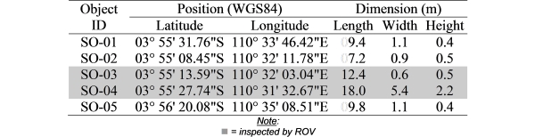
suspected objects recorded in Area-2 are listed in Table 2. From MBES
point cloud data, however, only SO-04 is understood to indicate
significant dimension, particularly its apparent height. No significant
height is detected from the rest of suspected objects.
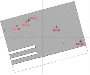
Figure 4 SSS mosaic with markers of
Suspected Object (SO) in Area-2
Table 2 List of position and dimension of suspected objects in Area-2
ROV deployment assisted by USBL positioning system and diving
operations by the Indonesian Navy diving team were conducted to identify
SO-03 and SO-04. These visual and manual inspections lead to a
conclusion that these two objects are not associated with any parts of
the airplane. The deployment of ROV and diver to validate SO-03
(although it does not indicate significant apparent height) is carried
out in order to provide control evidence. Sonar contacts in SO-04 are
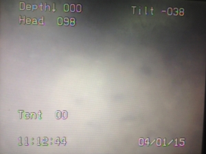
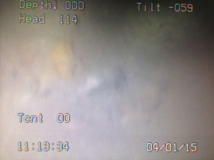
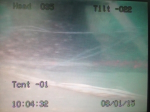
shown in Figure 5. Figure 6 shows ROV footage of SO-04 indicating an
object thought as wreck covered by coral colony. Relatively deep water
and strong current do not allow good visibility.
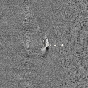
(a) SSS imagery |
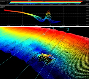
(b) MBES point cloud |
Figure 5 Sonar records of suspected object in SO-04
Figure 6 ROV photos showing wreck covered by corals in SO-04
3.3 Area-3
Eight sonar contacts were recorded by SSS and their apparent heights
were also measured by MBES, hence interpreted as suspected objects. ROV
deployment assisted by USBL positioning system and diving operations
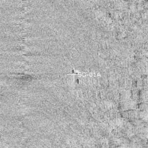
were conducted to verify six of them. Figure 7 shows suspected objects
in Area-3 as appear on SSS image mosaic. Table 3 shows list of the
corresponding suspected objects. Verification through visual detection
using ROV and manual inspection by divers confirmed that SO-01, SO-05,
and SO-06 are parts of the missing airplane. In particular, SO-05 is
identified as the tail. SO-01 is confirmed as seats and corpses. It is
validated that SO-06 are the body and wings.
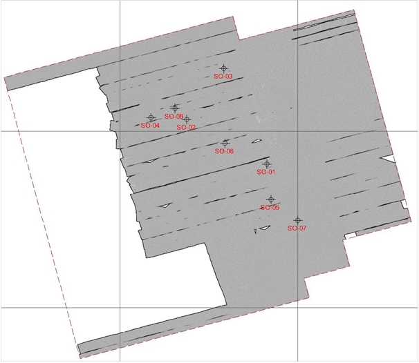
Figure 7 SSS mosaic with markers of Suspected Object (SO) in Area-3
Table 3 List of suspected objects in Area-3
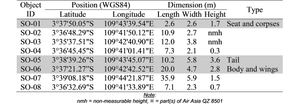
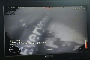
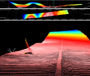
Figure 8 shows SSS image and MBES point cloud data of SO-05. The
corresponding ROV footage and underwater photograph taken by diver are
shown in Figure 9. It is validated that the object is the tail of Air
Asia QZ8501.
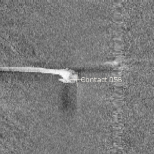
(a) SSS imagery |
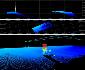
(b) MBES point cloud |
Figure 8 Sonar records of suspected object in SO-05
(a) ROV footage |
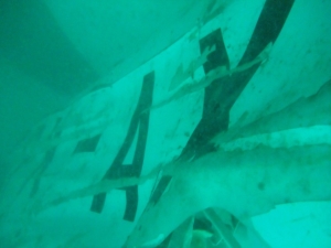
(b) Diver photograph |
Figure 9 Photos of suspected object in SO-05 identified as tail
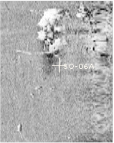
Figure 10 shows SSS image and MBES point cloud data of SO-01. It is
identified that these objects are seat and corpses. AKSLI vessel was
ordered to recover the object found in SO-01. Figure 11 shows the
underwater photograph of object found in SO-01 and the evacuation of
casualty on board of MGS GEOSURVEY vessel.
(a) SSS imagery |
(b) MBES point cloud |
Figure 10 Sonar records of suspected object in SO-01
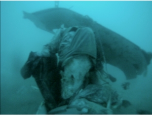
(a) Underwater photograph |
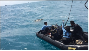
(b) Evacuation process |
Figure 11 Recovery of seat and corpses found in SO-01
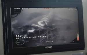
Figure 12 shows SSS image and MBES point cloud data of SO-06.
Validation of SO-06 is executed by ROV from MV Swift Rescue. It is
confirmed that these are main body and wings of the plane. Figure 13
shows ROV footage of object identified as SO-06.
(a) SSS imagery |
 (b)
MBES point cloud (b)
MBES point cloud |
Figure 12 Sonar records of suspected object in SO-06
Figure 13 ROV footages of suspected object in SO-06 (Photo: MV Swift
Rescue)
4. CLOSING REMARK
Sum up of important milestone of AKSLI mission reported in this paper
is visualized in Figure 14. Once the best approximate location is known,
regular hydrographic survey can accurately locate the searched objects.
SSS imagery provides isolation of underwater entities considered as
sonar contacts. Data from MBES point cloud help to approximate
significant apparent height of such sonar contacts. This leads to
identification of anomalous underwater object due to its contrast with
respect to the ambient. These sequences provide effective assistance to
an underwater SAR mission by narrowing the spatial extent of search
area. Experience from this search mission indicates that the operation
was able to locate the first object (i.e. SO-05) within 24 hours since
the arrival in the survey area and within the next 48 hours the other
object was located, i.e. SO-01.
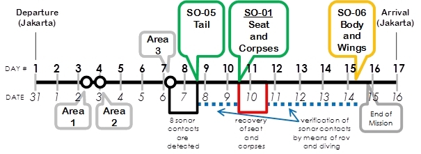
Figure 14 Time line of important milestone of AKSLI search survey
operation
In Figure 15, summary of detected heights of suspected objects from
Area-2 and Area-3 is visualized. Looking at the recorded heights of
suspected objects, it seems that anomalous heights of greater than 1.5 m
may lead to an approximation of non-natural objects. Red triangles in
Figure 15 indicate heights of objects measured by MBES that lead to
presence of parts of the missing airplane, as validated by direct
inspection.
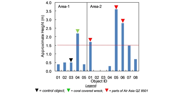
Figure 15 Summary of height of suspected object in Area-2 (01 to 05)
and Area-3 (01 to 08)
ACKNOWLEDGEMENT
This paper is based on AKSLI Corporate Social Responsibility Survey
Report (AKSLI, 2015). Credit goes to AKSLI, on-board technical crews,
and relevant aforementioned parties. AKSLI mission is also supported by
Geodesy Alumni Association (IAGD), Institut Teknologi Bandung (ITB).
Endorsement to personnel involved in the mission is given by the
Indonesian Surveyor Association (ISI). The preparation of this paper is
encouraged by AKSLI chairman, Mr. Sobri Syawie. The author is profoundly
saddened by the crash of Air Asia QZ8501.
REFERENCE
AKSLI, 2015. Search and Rescue of Air Asia QZ8501 by Using Side Scan
Sonar, Multi Beam Echo Sounder and Remotely Operated Vehicle, Java Sea
and Karimata Strait, Indonesia. Corporate Social Responsibility Survey
and Seafloor Mapping Community for Nation. Survey Report. Indonesian
Association of Marine Survey Contractors (Asosiasi Kontraktor Survei
Laut Indonesia - AKSLI). Jakarta, Indonesia.
BIOGRAPHICAL NOTES
Dr.rer.nat. Poerbandono is Associate Professor in Hydrography and
course coordinator of FIG/IHO/ICA Category A Hydrographic Surveyor
Profession Education Program at Geodesy and Geomatics Engineering Study
Program, Faculty of Earth Sciences and Technology, Institut Teknologi
Bandung (ITB), Indonesia.
CONTACTS
Dr.rer.nat. Poerbandono
Geodesy and Geomatics Engineering - ITB
Jalan Ganesha 10, Bandung 40132, INDONESIA
Telephone +62-22-2530701
Facsimile +62-22-2530702
Mobile +628112261764
Email poerbandono@gd.itb.ac.id
Website www.gd.itb.ac.id
|